
Wire Electrical Discharge Machining Introduction: Sodick AQ300L
This page offers a brief introduction to the capabilities and operation of the Sodick AQ300L Wire Electrical Discharge Machine (WEDM).

Wire electrical discharge machining is a non-contact based machining process in which material is cut from the workpiece using electricity carried by a wire. This machine uses a brass wire with a diameter of 0.0098″. Because there is no contact between the wire and the workpiece, the hardness of the workpiece becomes largely irrelevant. This machine is just as happy cutting super hard tool steel and carbide as it is cutting mild steel. It can cut aluminum, but the finish does not come out as nice due to the softer material, the particles tend to clog the filters, and it isn’t always the best way to machine an aluminum part since aluminum is so easy to machine by other means. Because it can cut very hard materials (the only real constraint is that the material must conduct electricity) a machine like this will often be used in industry for tool and die making. Punches and dies used in manufacturing processes are exposed to high loading, and as such they often require exceptionally wear resistant materials. Another key benefit of this machine is that it can create parts with exceptionally tight tolerances; 0.002″ RMS for a single pass, and 0.0002″ RMS for a refined 4-pass process. Also, the 4-axis movement of the top and bottom heads relative to each other allows the machine to cut entirely different patterns on the top and bottom of a workpiece.

Here the work tank can be seen at the bottom of the picture. This fills with the dielectric fluid (in this case deionized water) which is used to keep the workpiece cool and carry away debris from the cut. In the upper right of the picture the control system can be seen. This consists of a touchscreen computer display with a keyboard and mouse, a control panel to the left of that, and a remote unit which can be seen hanging below the computer.

With the tank open the work table is visible. The workpiece for any machining process is bolted to this table using the appropriate fixtures. Tooling for fixtures is one of the finer arts in machining. parts are not always straightforward, and determining the best way to secure an oddly shaped piece into the machine so that the part will come out correctly takes careful attention.

The wire has been threaded. The brass wire is stretched between the two heads of the machine, electrified, and moved along the path prescribed by the operator using G-code. It works kind of like a combination of a scroll saw and a plasma cutter. Kind of. I like to call it an industrial lightsaber.
A video of the machine in operation should give you a better perspective on just how it works. At the end of the video, note the colored bar. If the indicator is in the yellow region then the conditions are set too slow and time is being wasted. If the indicator is in the blue region then the conditions are set too fast and the wire could (will) break. If the indicator is in the green section then everything is A-OK.

Here the offset between the bottom and top heads is shown. This illustrates how the independent movement of these two heads can allow for tapers, and can create different patterns on the top and bottom of a part. The caveat to that is that the taper angle cannot exceed the geometric limitations of the machine, which as configured is approximately 10 degrees maximum.

Here is the control panel. The green “ENT” button is used to execute commands. Be very careful when pressing this button, as it can make the machine move. Always make sure that everyone is clear of the machine before pressing “ENT”. At the top of the picture is the Big Red Button. This is the emergency stop for the machine. If pressed, the power is cut to the machine instantly. Cutting will stop, the electricity to the wire will stop, movement will stop, and the computer will be powered down hard. There are multiple problems with this. First, is you press the Big Red Button because someone has gotten themselves physically stuck in the machine, you have just doomed them to stay stuck for another 10 to 15 minutes while we restart the computer and cycle the machine back on. There is no way to move the machine without the control computer; there is no manual override. In addition, the control computer is a modified Windows PC, and we all know how well Windows PCs take to having the plug pulled without shutting down properly. If you feel that you need to push the emergency stop in order to ensure safety, then do so, but be sure to consider the ramifications and make sure it is the best course of action to avoid increased injury. Below the Big Red Button there is a “Source” on and off button which boots the computer up and shuts it down, and a “Power” on and off button which turns the power to the machine on an off. The “Power” on and off are independent of the computer, so if you press the “Power” off the machine will stop moving and the electricity will stop while still leaving the computer as it was, allowing for a quicker recovery than the Big Red Button. Consider this as another option to stop the machine in an emergency; use your judgement and always act to ensure the safety of people first, and machine second.

The controls on the the remote unit are a copy of those on the lower part of the control panel. Above the “ENT” button are the red “OFF”, blue “ACK”, and red “HALT” buttons. HALT will pause the action that is being run, and pressing ENT again will un-pause it. This is a good way to stop the machine temporarily to examine some aspect of the job while still allowing the process to be easily resumed. The OFF button will stop the current action, and it will need to be restarted from the beginning. The ACK button is used to acknowledge messages that the machine presents to the operator, usually when something has gone wrong like a limit being exceeded or the wire breaking.
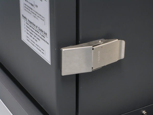
This is the latch that holds the tank closed. There is nothing that stops this latch from being opened when the machine is full of water, which would result in a deluge in the lab, and several student with failing grades. Always ensure that the tank has drained completely before opening the tank. It is usually best to let the instructor do this.

The next few photos document a sample job done of the WEDM machine. Here is a photo of the workpiece toe clamped to the table in the machine.

I wanted to use the more efficient “Close” flushing condition, so I used a feeler gauge to ensure that the upper head of the machine was within 0.004″ of the top of the workpiece. When doing this the Z-axis position must be adjusted slowly to make sure that the head isn’t crashed into the workpiece, which would overload the motor and shut down the machine. After I was done I zeroed the Z coordinate so that I could easily find the proper position.

Next I threaded the wire though the workpiece, and used a built in feature of the machine to locate the center of the reference hole. For this part, it was critical that the part be concentric to the reference hole, so I ran the hole center finding program several times to ensure accuracy.

With the machine located at the desired start location, both along the Z-axis and in the XY plane, I was ready to run the program.

The machine fills with deionized water, and the cutting process begins. The water turns dark and cloudy because of the metal debris that is being removed from the piece. The kerf of the cut is approximately 13 thousandths for steel, and up to 16 thousandths for aluminum.

The machine can be set to provide a graphical representation of its progress.

The final part came out to spec. This part was made with a 4-pass process, so a final grinding process was required to remove the small section where the piece was held into the machine, which could only be cut once.
I welcome your questions, comments, and concerns.